- Details
- Category: Tutorials
As mentioned in Part 1, the value of the fault loop impedance shall be able to generate enough fault current to activate any protective device.
What does this mean? The earth fault current must be high enough to trigger the automatic disconnection of a protective device within an specified time. If the value of the earth fault current is not within the tripping current of the protective device, then there will be no means of protective device will provide protection against touch voltage. At the location of the fault, there is a possibility that the full voltage is present in the equipment enclosure posing hazard to people with the increased touch voltage higher than 50 Vac.
- Details
- Category: Tutorials
What is "Earth Fault-Loop Impedance"? Why is it important?
Standards define "Earth Fault-Loop Impedance" as the impedance of the earth fault-current loop (active-to-earth loop) starting and ending at the point-of-earth fault.
It is important to know the earth fault-loop impedance of a circuit to ensure that during the occurence of a phase-to-earth fault, normally an insulation fault, the magnitude of the fault current is enough to cause the operation of the protective device within the required time particularly where the touch potential exceeds 50V a.c. or 120V ripple-free d.c.
- Details
- Category: Tutorials
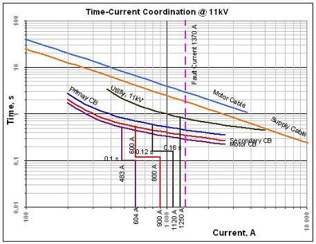
This is the final part of the tutorial creating for time-current current curves with Excel. We shall be able to attain a complete relay coordination similar to this following curve.
- Details
- Category: Tutorials
In this tutorial, we shall be able to create Normal Inverse curves from the formula given below (IEC). This formula has been used in so many coordination studies world wide. You can actually use it to coordinate your protection settings with your power supplier. Normally the time setting for the network protection will be provided by the power supplier. We shall be discussing this on the next tutorial.

Time-Current Formula
where
k = time, s
α, β = constants, see table below
I = Input Current
IO = Pickup setting
- Details
- Category: Tutorials
In this part of the tutorial, we shall be able to produce a Normal Inverse time-current curve. Given the values below, we will be plotting the values on an XY Scatter graph with data points connected without markers.
| I (A) | t (s) |
|---|---|
| 600 | 2.75 |
| 800 | 1.60 |
| 1200 | 1.01 |
| 1600 | 0.80 |
| 1600 | 0.80 |
| 1600 | 0.14 |
| 4800 | 0.14 |
| 4800 | 0.10 |
Try plotting the values and I presume that you will be getting a graph similar to Figure 1.

Figure 1
- Details
- Category: Tutorials
As electrical engineers, doing protective devices coordination is always a part of our tasks. You may say that I could always use ETAP or EDSA or SKM Power Tools to do the job.
If your company has the money to buy all these software, then you are right. The most important thing however is, do you know how to use the sophisticated power system analysis software.
At the end of this tutorial, the electrical engineer will be able to create coordination graphs for any particular application. This tutorial also aims to provide tips during the process.
The requirements of this tutorial are the following
- You have MS Excel - at least MS Excel 2003 - lower versions may do as well.
- You know how to use MS Excel
- You know how to create graphs.
This is a sample of coordination curve we shall be doing on the next part of the tutorial.

- Details
- Category: Tutorials
The Common specifications for high-voltage switchgear and controlgear standards ( IEC 60694:2002 ) tables 1 and 2 provide the rated insulation levels of switchgears and controlgears. In these tables, the withstand voltage applies at the standardized reference atmosphere (temperature, pressure and humidity) specified in IEC 60071-1.
The rated withstand voltage values for lightning impulse voltage (Up), switching impulse voltage (Us) (when applicable), and power-frequency voltage (Ud) shall be selected without crossing the horizontal marked lines. The rated insulation level is specified by the rated lightning impulse withstand voltage phase to earth.
- Details
- Category: Tutorials
In the initial part of this tutorial, we were able to calculate the size of the power factor correction capacitor bank required to improve the power factor of a plant from 0.75 lagging to 0.95 lagging. In this part of the tutorial, we shall be able to calculate the savings generated from the improved power factor.
Depending on the power utility company, the following values may vary.
Example : Utility Company A has the following charges.
Average Cost /khw : $0.09 (Other costs such as demand charges are already integrated in this value)
Power Factor Charges:
Below 0.80 lagging : +5.00 % x Total Energy Consumption
Above 0.90 lagging : -3.75 % x Total Energy Consumption
- Details
- Category: Tutorials
Note: This is the first part of the PF Correction tutorial series.
In industrial plants, induction motors comprises majority of the load. Without power factor correction, the nominal industrial plant overall power factor ranges from about 0.70 to 0.80 lagging.
A low power factor means that the I2R losses is high. Some electrical utility companies also penalize plant with low power factors as this leads to a high system loss. On the hand, plant with high power factor are given incentive discounts on the billing which will make any investment on a power factor correction equipment viable.
- Details
- Category: Tutorials
Type test (design test) is defined as the series tests which are made upon the completion of the development of a new equipment design to establish representative performance and to demonstrate compliance with the relevant standard. Once made, these tests need not be repeated unless the design is changed so as to modify its performance. In such a case only the relevant tests need be repeated.Type testing is normally done by a testing authority independent from the equipment manufacturer. The test authority will be issuing Type test certification for the particular equipment.Switchgears and controlgears could be classified as type-test assembly (TTA) or partially type test assembly (PTTA).
- Details
- Category: Tutorials
Selecting the right equipment to perform the right task during design is a tedious job. A very good example is the variable speed drive (VSD) versus Soft Starter(SS).
On low capacity drives (<25kW), there is no significant cost difference between the two equipment. In high capacity drive application (rating above 1MW) and moving into the medium voltage (6.6kV - 11kV), there will be significant difference in the total cost of ownership between the two equipment.
- Details
- Category: Tutorials
Lightning is a high-voltage discharge (usually negative) within clouds (intra-), to each other (inter-), or to the earth. The cloud-to-ground (CG) flash is the one we are usually concerned with lightning protection. The charged cells in clouds normally attract charges of opposite polarity on the earth's surface or on high objects located directly below them. When the charge reaches a critical level causing the insulation between cloud and earth breaks down, it develops a stepped ionized path, frequently to the earth, resulting in a high current discharge (stroke) that neutralizes, for the moment, these cloud and earth charges. The discharge current increases from zero to a maximum of 1 us to 10 us, and then declines to half the peak value of 20 us to 1000 us. Lightning flashes usually consist of a sequence of individual return strokes that transfer significant electrical charge usually from the cloud to earth.
- Details
- Category: Tutorials
The best things in life are free. This is what I felt when I am doing this exercise, comparing results from InterPSS with ETAP.
To verify on how an open source software match up to an expensive commercial software like ETAP, I tried comparing the results side by side. I used ETAP 5.5.6 and InterPSS 1.4.04 in my comparison.