![]()
This article is the first of a series in the selection of electrical cables.
Cable selection is an important part of electrical installation design. Selecting the correct size of cable could lower initial cost, lower operating cost, better voltage regulation notwithstanding the safety factor.
Cable parameters are provided in values per unit length, usually ohms per kilometer(Ω/km) for IEC or miles(Ω/mi) for North American Standards.
The following table illustrate the typical parameters for industrial cables
| Nominal conductor area (mm2) |
Single cores in trefoil |
3 cores | Approximate armouring resistance |
||
|---|---|---|---|---|---|
| Resistance at 90oC (ohm/km) |
Reactance at 50Hz |
Resistance at 90oC (ohm/km) |
Reactance at 50Hz |
GSWB at 60oC 3–4 cores (ohm/km) |
|
| 1.5 | 15.6 | 0.185 | 15.6 | 0.118 | 46.2 |
| 2.5 | 9.64 | 0.173 | 9.64 | 0.111 | 51.3 |
| 4 | 5.99 | 0.163 | 5.99 | 0.108 | 60.3 |
| 6 | 3.97 | 0.153 | 3.97 | 0.105 | 30.5 |
| 10 | 2.35 | 0.148 | 2.35 | 0.0983 | 36.7 |
| 16 | 1.48 | 0.134 | 1.48 | 0.0933 | 23.1 |
| 25 | 0.936 | 0.125 | 0.936 | 0.0892 | 28.1 |
| 35 | 0.674 | 0.121 | 0.674 | 0.0867 | 10.43 |
| 50 | 0.499 | 0.118 | 0.499 | 0.0858 | 11.81 |
| 70 | 0.344 | 0.112 | 0.344 | 0.0850 | 13.61 |
| 95 | 0.271 | 0.108 | 0.271 | 0.0825 | 10.87 |
| 120 | 0.214 | 0.106 | 0.214 | 0.0808 | 11.92 |
| 150 | 0.175 | 0.105 | 0.175 | 0.0808 | 7.38 |
| 185 | 0.140 | 0.105 | 0.140 | 0.0808 | 8.15 |
| 240 | 0.108 | 0.103 | 0.108 | 0.0800 | 8.94 |
| 300 | 0.087 | 0.101 | 0.087 | 0.0800 | 10.10 |
| 400 | 0.069 | 0.0992 | 0.069 | 0.0795 | 10.00 |
Derivation of Voltage Drop Formula
A short cable voltage drop in AC systems is provided by the formula
Vd = IR cosØ + IX sinØ
where:
Vd = Voltage drop per phase, volts
Ø = Load power factor angle
IR cosØ = Voltage drop component on the cable resistance
IX sinØ = Voltage drop component on the cable reactance
You might be wondering where this formula came from. Actually, this formula is just an approximation. We shall going through the process of deriving this formula to better understand it.
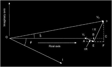
Considering the following vector diagram:

where:
Vs = Sending end voltage per phase
Vr = Receiving end voltage per phase
I = Load current
R = Cable resistance
X = Cable reactance
Ø = Load power factor angle
AB = IR cosØ
BE = CF = IR cosØ
BC = EF = IX sinØ
DF = IX cosØ
AC = AB + BC = AB + EF
AC = IR cosØ + IX sinØ
DC = DF - CF = DF - BE
DC = IX cosØ - IR sinØ
Vs = OD = √(OA + AB + BC)2 + (DF - BE)2
Unless the cable is very long, the imaginary axis component of the voltage is very small compared to the real axis component.
(OA + AB + BC) >> (DF - BE)
thus the sending end voltage will be
Vs = (OA + AB + BC)
Vs = Vr + IR cosØ + IX sinØ volts/phase
From the above formula, the voltage drop on a per phase basis will be
Vd = Vs - Vr
Vd = IR cosØ + IX sinØ volts/phase per unit length
That is how the voltage drop formula was derived.
Normally, voltage drop is expressed as a percentage of the sending end line-to-line voltage. The formula will be

where:
V = sending end line-to-line voltage
R = rl, where r is the unit resistance in ohms/km
X = xl, where x is the unit reactance in ohms/km
as published in cable data publications.
For Part 2, we shall be providing real world examples on voltage drop calculations.
References:
- Handbook of Electrical Engineering For Practitioners in the Oil, Gas and Petrochemical Industry
Alan L. Sheldrake - Electrical Engineer's Reference Book Sixteenth edition
M. A. Laughton